Issues installing Netbox web service

Hi all

Today I was trying to install netbox on a Linux server. I have done it before but just for testing and never connected it to apache or nginx for a production enviorment. I used the guide supplied in the official manual but I managed for some reason to fail completely. Not sure where the error was if I just did something completely stupid orthe manual was just incomplete. You can check the manual here if you need.

My issue was that when all the commands I had to run for the HTTPS server according to the manual I still got an error. The lovely 503 Service unavailable.

Service Unavailable
The server is temporarily unable to service your request due to maintenance downtime or capacity problems. Please try again later.

Apache/2.4.41 (Ubuntu) Server at netbox.example.com Port 443

When I checked the service I got the following response:

manager@ubuntults:~$ systemctl status netbox
● netbox.service - NetBox WSGI Service
     Loaded: loaded (/etc/systemd/system/netbox.service; enabled; vendor preset>
     Active: activating (auto-restart) (Result: exit-code) since Tue 2020-05-26>
       Docs: https://netbox.readthedocs.io/en/stable/
    Process: 1217 ExecStart=/usr/local/bin/gunico --pid /var/tmp/netbox.pid --p>
   Main PID: 1217 (code=exited, status=203/EXEC)
lines 1-6/6 (END)

In the active section you can see that it says activating and not activated and Main PID: gives me: (code=exited, status=203/EXEC)

This tells me that the system has issues executing the files for starting the service. I followed this up by going to the service file where all the settings are made for the service.

sudo nano /etc/systemd/system/netbox.service

I then continued to look at the execution parameters for the service.

ExecStart=/opt/netbox/venv/bin/gunicorn --pid /var/tmp/netbox.pid --pythonpath /opt/netbox/netbox --config /opt/netbox/gunicorn.py netbox.wsgi

When I checked for the gunicorn file in the filesystem I couldn’t find the file gunicorn in /opt/netbox/venv/bin/. Therefor I entered the command “which gunicorn” that returns the correct path for gunicorn to me.

manager@ubuntults:~$ which gunicorn
/usr/local/bin/gunicorn

The correct syntax would then be:

ExecStart=/usr/local/bin/gunicorn --pid /var/tmp/netbox.pid --pythonpath /opt/netbox/netbox --config /opt/netbox/gunicorn.py netbox.wsgi

When you have done the change you need to update the service like I have done below:

manager@ubuntults:~$ sudo nano /etc/systemd/system/netbox.service
[sudo] password for manager:
manager@ubuntults:~$ sudo nano /etc/systemd/system/netbox.service
manager@ubuntults:~$ systemctl daemon-reload
==== AUTHENTICATING FOR org.freedesktop.systemd1.reload-daemon ===
Authentication is required to reload the systemd state.
Authenticating as: manager
Password:
==== AUTHENTICATION COMPLETE ===
manager@ubuntults:~$ systemctl restart netbox
==== AUTHENTICATING FOR org.freedesktop.systemd1.manage-units ===
Authentication is required to restart 'netbox.service'.
Authenticating as: manager
Password:
==== AUTHENTICATION COMPLETE ===
manager@ubuntults:~$

Now the server should work perfectly 🙂

I couldn’t have solved it hadn’t it been for this post and the answer from Russell Molimock. That put me on the correct track for finding the issue 🙂

Can’t upload image to wordpress due to large size

Hi

In my new job I have been working a little bit with cPanel and WordPress. It sounds easy enough and both of the products are easy enough normally. But there is always one of these fun errors that just makes you wonder. What the f*** could be the problem here. Everything seems fine but everything is so wrong.

When the users where going to upload files we changed the upload limit on the PHP server and everything should be working fine. The users should be able to upload files up to 250 MB. At least that was what I was thinking. But no matter what I did I got the following error up: “Post-processing of the image failed. If this is a photo or a large image, please scale it down to 2500 pixels and upload it again”

My picture was below this size and I belive I tried every single solution to this issue I could find on the internet. The only solution that worked for me was the plugin Add from Server, with this plugin I was able to get my pictures to the libary.

After hours of googling and talking to coworkers we suddenly discovered that cPanel is not delivered with mod_fcgid turned on in Apache. This simple feature took me ages to find out. In addition you need to install the imagick module.

imagick you can install in cPanel by go to Software -> Module Installer in the left menu. Manage the PHP PECL and search and install imagick for all needed PHP versions (at least where you run WordPress).

Then you need to enable mod_fcgid. This can be done in Software -> Easy Apache 4 on the left side menu and choose Customize on the menu showing. Now you can go to Apache modules and search for mod_fcgid. When this module is enabled you can try to upload again. Hopefully it works now!

Be aware that the changes done here needs to be done by your hosting provider and unless you have access to the WHM console you need to forward them this article to fix the issues.

Centos 7 with cPanel loose network config

Today I have been struggeling with cPanel. I did install an Centos 7 server with cPanel WHM on it. I followed the instructions from tecmint and it was pretty straight forward! I have to admit, that was my thought all the way until I rebooted the server with an software update.

At firdst I didn’t know what happened. I thought it was a firewall issue etc. But I couldn’t find any issues. When I finally started to check the server more closely I discovereed when running ifconfig that there where no network card configured with the correct IP. I then moved further and tried to restarting the network service with the command:

systemctl restart network.service

When doing this I got an error message :
Job for network.service failed because the control process exited with error code. See “systemctl status network.service” and “journalctl -xe” for details.

Checking “systemctl status network.service” gave me the following error message:

Failed to start LSB: Bring up/down networking.

This led me out on a desperate google search that lasted for a couple of hours. I found alot of articles that could be helpful but none that helped me. Or I did, in the end but it still felt like forever. I had read something similear to the solution below on my google searches. But those articles only said I needed to touch the network file (just create an empty file). But according to the forum post below I needed to add the commands below to /etc/sysconfig/network file.

NETWORKING=yes
GATEWAY=XXX.XXX.XXX.XXX

XXX.XXX.XXX.XXX represent the IP of the gateway for the CentOS server. When the file is edited I did a reboot and it all worked again! 🙂 I tried to restart the network.service but for some reason I had to do a complete reboot for it to work.

Forum post

Management access list on Juniper SRX

Sometimes you need to restrict access to your Juniper SRX firewall, or lets say you should always restrict the access to the firewall when it’s connected to the internet.

So now I’ll show you how to limit the traffic to your firewall to only be accessible from the allowed IP’s or IP ranges. In the first part we will insert the subnets and IP’s into a prefix list called manager.

set policy-options prefix-list manager-ip 192.168.4.254/32
set policy-options prefix-list manager-ip 10.0.0.0/8

The next part will tell the firewall to discard requests done to the firewall except to the IP’s in the prefix list above named manager. The filter will only apply to the services below so make sure to not remove any of the services you wan’t to limit access to. The last line in the snippet below is a block command to block off all the traffic hitting this term.

set firewall filter manager-ip term block_non_manager from source-address 0.0.0.0/0
set firewall filter manager-ip term block_non_manager from source-prefix-list manager-ip except
set firewall filter manager-ip term block_non_manager from protocol tcp
set firewall filter manager-ip term block_non_manager from destination-port ssh
set firewall filter manager-ip term block_non_manager from destination-port https
set firewall filter manager-ip term block_non_manager from destination-port telnet
set firewall filter manager-ip term block_non_manager from destination-port http
set firewall filter manager-ip term block_non_manager then discard

In the end we will accept everything to allow everything and by that only allowing access to the IP’s mentioned since they where excepted from the prevoius term that was blocked in the end.

set firewall filter manager-ip term accept_everything_else then accept

At the very end we add the filter to the loopback interface. By doing this all traffic will hit the rule, you can also add it to seperate interfaces if you only want to limit the traffic from certain interfaces.

set interfaces lo0 unit 0 family inet filter input manager-ip

When you have done that the firewall is a bit more secure than before. Hopefully I will have the chance to write how to secure your Juniper SRX even more later on. Below is all the code in one snippet for easy cut and paste.

set policy-options prefix-list manager-ip 192.168.4.254/32
set policy-options prefix-list manager-ip 10.0.0.0/8
set firewall filter manager-ip term block_non_manager from source-address 0.0.0.0/0
set firewall filter manager-ip term block_non_manager from source-prefix-list manager-ip except
set firewall filter manager-ip term block_non_manager from protocol tcp
set firewall filter manager-ip term block_non_manager from destination-port ssh
set firewall filter manager-ip term block_non_manager from destination-port https
set firewall filter manager-ip term block_non_manager from destination-port telnet
set firewall filter manager-ip term block_non_manager from destination-port http
set firewall filter manager-ip term block_non_manager then discard
set firewall filter manager-ip term accept_everything_else then accept
set interfaces lo0 unit 0 family inet filter input manager-ip

Source:
https://www.juniper.net/documentation/en_US/junos/topics/example/permitted-ip-configuring.html

Using python and SSH

Previously I have written a post about running telnet with Python. As everyone knows telnet is not the most secure protocol to manage devices. So I want to help you guys out with connecting to devices with SSH using python.

In this example I will be using fabric. Fabric is a python libary that helps you send SSH commands to devices. You can read more on their website about the libary: http://www.fabfile.org/

pip3 install fabric

Since I’m running python3 on my computer I run pip3, if you have installed python2.X you just need to have pip as the first word and not pip3 in the command.

from fabric import Connection
c = Connection(host = '10.78.23.12', user = 'username', connect_kwargs = {'password':'password'})
result = c.run('show version')
print(result)

The first line imports the module needed for connecting using SSH from the fabric libary.
Then the connection to the host is performed with ip, username and password. The last two lines is a variable where the command is added to and a print command to display the information in the variable. The command in this script is just a simple show version to display the information on a cisco switch.

Convert from Mobility Express to Lightweight AP (CAPWAP)

If you have an Mobility Express AP that you wan’t to connect to another ME or a WLC controller you can easily convert it to a lighweight or a CAPWAP AP.

Connect to the AP using SSH or the console port. When you are connected go to the enable mode and enter the following command.

ap-type capwap

The AP will now restart, when it’s booted it will connect to a WLC or another ME AP on the network.

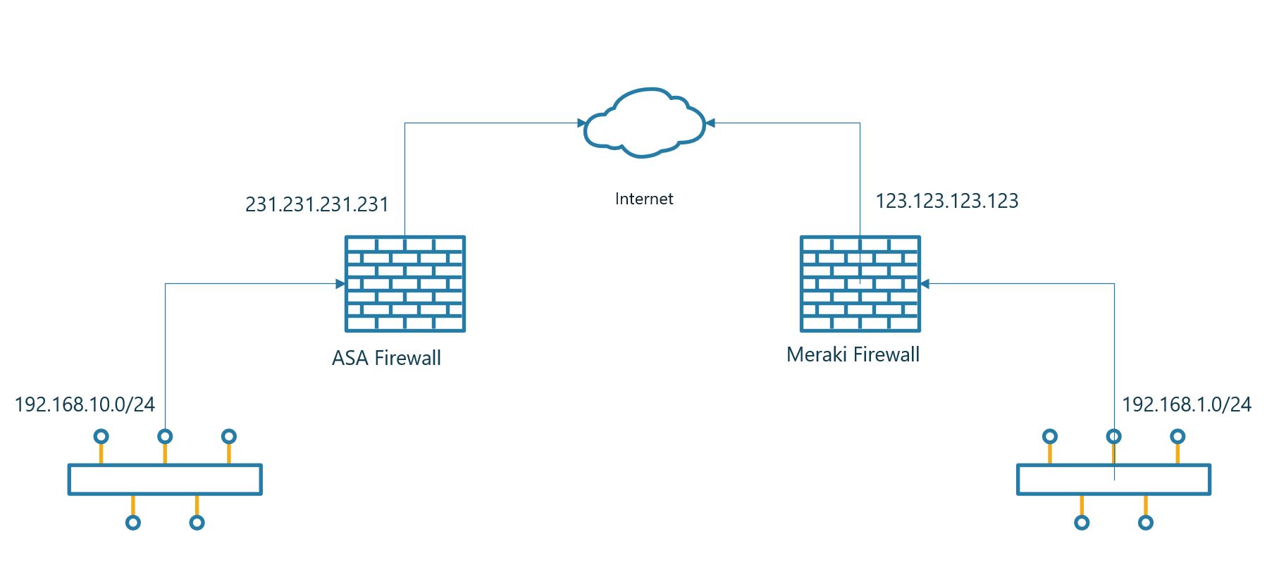
Site to Site VPN between Meraki MX and Cisco ASA 5508

Hi all

VPN’s are always a pain in the ass when it comes to different vendors and OS. Even if both Meraki and ASA is part of the Cisco brand there is still quite a few differences in the setup and as always alot of ways to do it incorrectly.

Let’s start with the ASA end of the link. The first thing we need to do is set up the IKE profile. Meraki uses only IKEv1 so there is no need for IKEv2.

crypto ikev1 enable outside
 crypto ikev1 policy 10
 authentication pre-share
 encryption 3des
 hash sha
 group 2
 lifetime 12800

Define the networks you wan’t to have on each end of the Meraki firewall.

 object network OBJ-ASA-Site
 subnet 192.168.10.0 255.255.255.0
 object network OBJ-Meraki-Site
 subnet 192.168.1.0 255.255.255.0

Now we will make sure that the traffic that is intended for the VPN is passed trough the tunnel. In the NAT rule the traffic is originating from the interface labeled server.

access-list MERAKI-INTERESTING-TRAFFIC extended permit ip object OBJ-ASA-Site object OBJ-Meraki-Site
nat (server,outside) source static OBJ-ASA-Site OBJ-ASA-Site destination static OBJ-Meraki-Site OBJ-Meraki-Site no-proxy-arp route-lookup

We will have to let the ASA know where to terminate the tunnel. Including the preshared key. It’s important to change the preshared key and use something a bit more secure.

tunnel-group 123.123.123.123 type ipsec-l2l
 tunnel-group  123.123.123.123  ipsec-attributes
 pre-shared-key supersecret
 isakmp keepalive threshold 10 retry 2

Finally we have to put everything together and let the ASA know where to terminate the VPN tunnel.

crypto ipsec ikev1 transform-set MERAKI-TRANSFORM esp-aes-256 esp-sha-hmac
 !
 crypto map CRYPTO-MAP 1 match address MERAKI-INTERESTING-TRAFFIC
 crypto map CRYPTO-MAP 1 set peer 123.123.123.123
 crypto map CRYPTO-MAP 1 set ikev1 transform-set MERAKI-TRANSFORM
 crypto map CRYPTO-MAP interface outside

Below is all the commands in one go to make it easier for a copy/paste.

crypto ikev1 enable outside
 crypto ikev1 policy 10
 authentication pre-share
 encryption 3des
 hash sha
 group 2
 lifetime 12800
 !
 object network OBJ-ASA-Site
 subnet 192.168.10.0 255.255.255.0
 object network OBJ-Meraki-Site
 subnet 192.168.1.0 255.255.255.0
 !
 access-list MERAKI-INTERESTING-TRAFFIC extended permit ip object OBJ-ASA-Site object OBJ-Meraki-Site
 nat (server,outside) source static OBJ-ASA-Site OBJ-ASA-Site destination static OBJ-Meraki-Site OBJ-Meraki-Site no-proxy-arp route-lookup
 !
 tunnel-group 123.123.123.123 type ipsec-l2l
 tunnel-group  123.123.123.123  ipsec-attributes
 pre-shared-key supersecret
 isakmp keepalive threshold 10 retry 2
 !
 crypto ipsec ikev1 transform-set MERAKI-TRANSFORM esp-aes-256 esp-sha-hmac
 !
 crypto map CRYPTO-MAP 1 match address MERAKI-INTERESTING-TRAFFIC
 crypto map CRYPTO-MAP 1 set peer 123.123.123.123
 crypto map CRYPTO-MAP 1 set ikev1 transform-set MERAKI-TRANSFORM
 crypto map CRYPTO-MAP interface outside

Then let’s move over to the Meraki part. This part is really easy compared to the ASA part. There isn’t much configuration to do on the Meraki to get everything up and working,.

The first thing you need to do is go to Security Appliance -> Configure -> Site-to-.Site VPN. Select Hub in the options list.

Select the networks that should be routed trough the VPN. In the previous config we said that 192.168.1.0/24 should be routed from the Meraki site.

The last part would be to configure the VPN settings on the Meraki. First column you enter a name for the connection. Secondly you need to enter the IP for the ASA firewall. In the third column you decide what networks should be sent over the VPN. The same network that we defined as OBJ-ASA-Site in the ASA config. Leave the IPSec policies as Default, the connection should come up with the Default setting. At last you enter the pre shared key, press save and you should have a VPN connection.

Playing with the Meraki API

Lately I have started playing with the Meraki API. The API gives us the possibility to tweak and manage whatever you want to do on the Meraki devices.

To begin with you need to get the API code from the Meraki Dashboard. You can get the API code if you click on your username in the upper right corner and then proceed to My Profile. In that window you can enable and generate API keys for your scripts.

The first script you should use is the code below. This should give you a list of organizations that you have access to with the user account you generated the API key with. Normally you only have 1 organization but many might have several organizations in the list.

curl --request GET -L \
  --url https://api.meraki.com/api/v0/organizations \
  --header 'X-Cisco-Meraki-API-Key: <API key>'

This could create the follwoing output:

[{"id":"692333","name":"Organization 1"},{"id":"293843","name":"Organization 2"},{"id":"551234","name":"Organization 3"},{"id":"123476","name":"Organization 4"}]

At this point you can choose what organisation you want to create the API for. You need to take the ID and add it to the end of the URL. If I want to towrk with organization 3 I would use 551234 as the ID. After the ID you need to add networks to list the networks for the organization. I ahve added an example below:

curl --request GET -L \
  --url https://api.meraki.com/api/v0/organizations/551234/networks \
  --header 'X-Cisco-Meraki-API-Key: <API key>'

From that you should get the following output:

[{"id":"L_662029145123456789","organizationId":"551234","name":"Site 1","timeZone":"Europe/Oslo","tags":null,"type":"combined","disableMyMerakiCom":false,"disableRemoteStatusPage":true}]

You now have all the information needed to start playing around with API’s on Meraki. Meraki got alot of documentation showing what you can do. You can find the documentation here.

As an example on what you can do I can show you how to enable and disable an SSID on a network. In the Meraki documentation for SSID’s you find the various settings that you can configure. In this example I only want to change the enabled or disabled settings for the SSID. In the data-binary setting you switch between false and true to swap between disabled and enabled setting for the SSID.

curl -L -H 'X-Cisco-Meraki-API-Key: <API key>' 
  -X PUT -H 'Content-Type: application/json' 
  --data-binary '{"enabled":true}' 'https://api.meraki.com/api/v0/organizations/551234/networks/L_662029145123456789/ssids/1'

Convert Cisco Lightweight AP to Mobility Express

Hi all

Today I’m going to write a short post on how to convert a lightweight AP to an Mobility Express AP. It’s a very simple process and only takes a few minutes to complete.

First you need to download the ME image from the Cisco webpage. Extract the compressed file to a TFTP server.

Login to the AP with console access using Cisco / Cisco as username and password (this is offcourse only if you haven’t changed the password on the AP.

ap-type mobility-express tftp://<TFTP Server IP>/<filename>

When the file is uploaded the AP will reboot and load the new image. The AP will use 2 IP’s. 1 for the ME and 1 for the AP.

During my upgrade I had one issue. It failed repeatedly and I worked a while before I discovered the reason.

Image transfer complete.
Image downloaded, writing to flash...
do CHECK_ME, part1 is active part
upgrade.sh: Error: image not found.
+ do_upgrade CHECK_ME
+ [ ! -r /tmp/part.tar ]
+ loudlog Error: image not found.
+ logger -p 0 -t upgrade Error: image not found.
+ echo upgrade.sh: Error: image not found.
upgrade.sh: Error: image not found.
+ return 1
+ status=1
+ set +x
Error: Image update failed.

I read on the internet that this error could be caused due to lack of space. I had free space left so I could quickly rule that issue out. I have another ME in the same network, it seems that the ME image can’t be uploaded when there is an ME of the same L2 network as the ME you are trying to install. The issue I had dissapeared when I disconnected the other ME.

After the upgrade has been completed the ME will reboot and start a setup wizard.

Enter Administrative User Name (24 characters max): admin
Enter Administrative Password (3 to 127 characters): ********
Re-enter Administrative Password                 : ********
System Name [Cisco-dcf7.193e.4c00] (24 characters max): hostname
Enter Country Code list (enter 'help' for a list of countries) [US]: NO
Configure a NTP server now? [YES][no]: yes
Use default NTP servers [YES][no]:
Enter timezone location index (enter 'help' for a list of timezones): 14
Management Interface IP Address Configuration [STATIC][dhcp]: dhcp
Create Management DHCP Scope? [yes][NO]:
Employee Network Name (SSID)?: SSIDName
Employee Network Security? [PSK][enterprise]:PSK
Employee PSK Passphrase (8-63 characters)?: ***********
Re-enter Employee PSK Passphrase: ***********
Enable RF Parameter Optimization? [YES][no]:
Client Density [TYPICAL][Low][High]:
Traffic with Voice [NO][Yes]:

Configuration correct? If yes, system will save it and reset. [yes][NO]: yes

Configuration saved!

There is a few things that you need to get correct when going trough the options. The first one is country code. This is important to have correct freqency since it need to meet the local regulations. Since my AP’s are in Norway I choose NO as the country code.

The second one is the management interface. You can choose to have it set to static or dhcp. I normally set these ME’s up for clients and configure them with DHCP. If you choose DHCP it’s important to note the correct DHCP address when the ME boots up. As previously mentioned the AP will request 2 IP’s. 1 for the ME and 1 for the CAPWAP AP.. After the bootup you should see the following output

[*08/01/2019 17:24:33.6830] ethernet_port wired0, ip 192.168.50.108, netmask 255.255.255.0, gw 192.168.50.1, mtu 1500, bcast 192.168.50.255, dns1 195.159.0.100, dns2 8.8.8.8, domain hjortsenter.internal, vid 0, static_ip_failover false, dhcp_vlan_failover false
[*08/01/2019 17:24:33.6930] chatter: MeshNat: config_ip IP=192.168.50.108 mask=255.255.255.0 GW=192.168.50.1
[*08/01/2019 17:24:38.7614] ethernet_port wired0, ip 192.168.50.110, netmask 255.255.255.0, gw 192.168.50.1, mtu 1500, bcast 192.168.50.255, dns1 195.159.0.100, dns2 8.8.8.8, domain test.internal, vid 0, static_ip_failover false, dhcp_vlan_failover false
[*08/01/2019 17:24:38.7814] chatter: MeshNat: config_ip IP=192.168.50.110 mask=255.255.255.0 GW=192.168.50.1
[*08/01/2019 17:24:41.8004] AP IPv4 Address updated from 0.0.0.0 to 192.168.50.110

The first IP in my example is the IP for the ME (192.168.50.108)
The last IP is for the CAPWAP (192.168.50.110)

Cisco switch tries to download file from TFTP

Hi again all

When you retrieve an older Cisco switch it normally tries to download a new config file from a TFTP server. If you do not have hands on the switch it’s an easy way for setting it up. You simply add a file named switch-confg, network-confg, ciscortr.cfg or cisconet.cfg. If you do that the config will be downloaded to the switch. Below you can see the switch trying to download the file but it can’t. The reason for this is that you need to issue a command for this to stop.

no service config 

If the no service config command is issued the following entries should stop in the log.

Apr 24 2011 13:47:24.645 UTC: %SYS-4-CONFIG_RESOLVE_FAILURE: System config parse from (tftp://255.255.255.255/switch-confg) failed
Apr 24 2011 13:48:06.656 UTC: %SYS-4-CONFIG_RESOLVE_FAILURE: System config parse from (tftp://255.255.255.255/ciscortr.cfg) failed
Apr 24 2011 13:48:22.369 UTC: %SYS-4-CONFIG_RESOLVE_FAILURE: System config parse from (tftp://255.255.255.255/network-confg) failed
Apr 24 2011 13:49:04.375 UTC: %SYS-4-CONFIG_RESOLVE_FAILURE: System config parse from (tftp://255.255.255.255/cisconet.cfg) failed
Apr 24 2011 13:58:48.668 UTC: %SYS-4-CONFIG_RESOLVE_FAILURE: System config parse from (tftp://255.255.255.255/switch-confg) failed
Apr 24 2011 13:59:30.679 UTC: %SYS-4-CONFIG_RESOLVE_FAILURE: System config parse from (tftp://255.255.255.255/ciscortr.cfg) failed
Apr 24 2011 13:59:46.392 UTC: %SYS-4-CONFIG_RESOLVE_FAILURE: System config parse from (tftp://255.255.255.255/network-confg) failed
Apr 24 2011 14:00:28.403 UTC: %SYS-4-CONFIG_RESOLVE_FAILURE: System config parse from (tftp://255.255.255.255/cisconet.cfg) failed
Apr 24 2011 14:10:12.691 UTC: %SYS-4-CONFIG_RESOLVE_FAILURE: System config parse from (tftp://255.255.255.255/switch-confg) failed
Apr 24 2011 14:10:54.707 UTC: %SYS-4-CONFIG_RESOLVE_FAILURE: System config parse from (tftp://255.255.255.255/ciscortr.cfg) failed
Apr 24 2011 14:11:10.420 UTC: %SYS-4-CONFIG_RESOLVE_FAILURE: System config parse from (tftp://255.255.255.255/network-confg) failed
Apr 24 2011 14:11:52.431 UTC: %SYS-4-CONFIG_RESOLVE_FAILURE: System config parse from (tftp://255.255.255.255/cisconet.cfg) failed
Apr 24 2011 14:21:36.719 UTC: %SYS-4-CONFIG_RESOLVE_FAILURE: System config parse from (tftp://255.255.255.255/switch-confg) failed
Apr 24 2011 14:22:18.735 UTC: %SYS-4-CONFIG_RESOLVE_FAILURE: System config parse from (tftp://255.255.255.255/ciscortr.cfg) failed
Apr 24 2011 14:22:34.443 UTC: %SYS-4-CONFIG_RESOLVE_FAILURE: System config parse from (tftp://255.255.255.255/network-confg) failed
Apr 24 2011 14:23:16.564 UTC: %SYS-4-CONFIG_RESOLVE_FAILURE: System config parse from (tftp://255.255.255.255/cisconet.cfg) failed
Apr 24 2011 14:33:00.747 UTC: %SYS-4-CONFIG_RESOLVE_FAILURE: System config parse from (tftp://255.255.255.255/switch-confg) failed
Apr 24 2011 14:33:42.758 UTC: %SYS-4-CONFIG_RESOLVE_FAILURE: System config parse from (tftp://255.255.255.255/ciscortr.cfg) failed
Apr 24 2011 14:33:58.597 UTC: %SYS-4-CONFIG_RESOLVE_FAILURE: System config parse from (tftp://255.255.255.255/network-confg) failed
Apr 24 2011 14:34:40.613 UTC: %SYS-4-CONFIG_RESOLVE_FAILURE: System config parse from (tftp://255.255.255.255/cisconet.cfg) failed
Apr 24 2011 14:44:24.770 UTC: %SYS-4-CONFIG_RESOLVE_FAILURE: System config parse from (tftp://255.255.255.255/switch-confg) failed
Apr 24 2011 14:45:06.796 UTC: %SYS-4-CONFIG_RESOLVE_FAILURE: System config parse from (tftp://255.255.255.255/ciscortr.cfg) failed
Apr 24 2011 14:45:22.630 UTC: %SYS-4-CONFIG_RESOLVE_FAILURE: System config parse from (tftp://255.255.255.255/network-confg) failed
Apr 24 2011 14:46:04.636 UTC: %SYS-4-CONFIG_RESOLVE_FAILURE: System config parse from (tftp://255.255.255.255/cisconet.cfg) failed
Apr 24 2011 14:55:48.808 UTC: %SYS-4-CONFIG_RESOLVE_FAILURE: System config parse from (tftp://255.255.255.255/switch-confg) failed
Apr 24 2011 14:56:30.814 UTC: %SYS-4-CONFIG_RESOLVE_FAILURE: System config parse from (tftp://255.255.255.255/ciscortr.cfg) failed
Apr 24 2011 14:56:46.648 UTC: %SYS-4-CONFIG_RESOLVE_FAILURE: System config parse from (tftp://255.255.255.255/network-confg) failed
Apr 24 2011 14:57:28.659 UTC: %SYS-4-CONFIG_RESOLVE_FAILURE: System config parse from (tftp://255.255.255.255/cisconet.cfg) failed
Apr 24 2011 15:00:55.742 UTC: %SEC_LOGIN-5-LOGIN_SUCCESS: Login Success [user: Cisco] [Source: 10.20.10.201] [localport: 23] at 15:00:55 UTC Sun Apr 24 2011
Apr 24 2011 15:00:58.557 UTC: %SYS-5-PRIV_AUTH_PASS: Privilege level set to 15 by Cisco on vty1 (10.20.10.201)
Apr 24 2011 15:00:58.557 UTC: %PARSER-5-CFGLOG_LOGGEDCMD: User:Cisco  logged command:!exec: enable