Site to Site VPN between Meraki MX and Cisco ASA 5508

Hi all

VPN’s are always a pain in the ass when it comes to different vendors and OS. Even if both Meraki and ASA is part of the Cisco brand there is still quite a few differences in the setup and as always alot of ways to do it incorrectly.

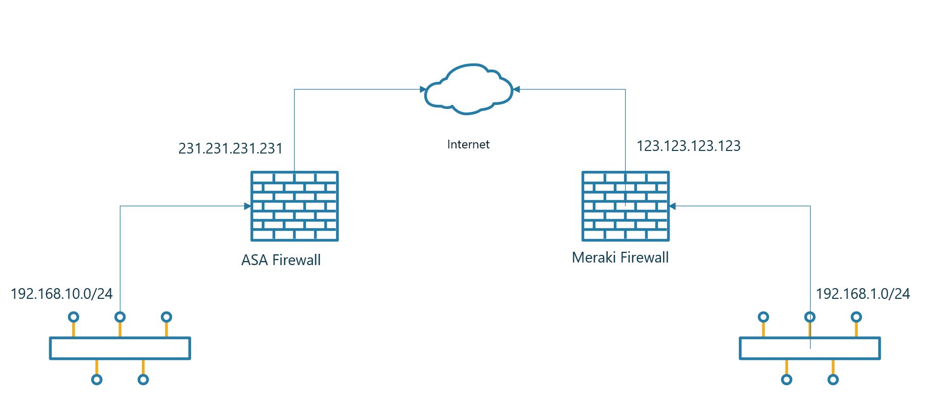
Let’s start with the ASA end of the link. The first thing we need to do is set up the IKE profile. Meraki uses only IKEv1 so there is no need for IKEv2.

crypto ikev1 enable outside
 crypto ikev1 policy 10
 authentication pre-share
 encryption 3des
 hash sha
 group 2
 lifetime 12800

Define the networks you wan’t to have on each end of the Meraki firewall.

 object network OBJ-ASA-Site
 subnet 192.168.10.0 255.255.255.0
 object network OBJ-Meraki-Site
 subnet 192.168.1.0 255.255.255.0

Now we will make sure that the traffic that is intended for the VPN is passed trough the tunnel. In the NAT rule the traffic is originating from the interface labeled server.

access-list MERAKI-INTERESTING-TRAFFIC extended permit ip object OBJ-ASA-Site object OBJ-Meraki-Site
nat (server,outside) source static OBJ-ASA-Site OBJ-ASA-Site destination static OBJ-Meraki-Site OBJ-Meraki-Site no-proxy-arp route-lookup

We will have to let the ASA know where to terminate the tunnel. Including the preshared key. It’s important to change the preshared key and use something a bit more secure.

tunnel-group 123.123.123.123 type ipsec-l2l
 tunnel-group  123.123.123.123  ipsec-attributes
 pre-shared-key supersecret
 isakmp keepalive threshold 10 retry 2

Finally we have to put everything together and let the ASA know where to terminate the VPN tunnel.

crypto ipsec ikev1 transform-set MERAKI-TRANSFORM esp-aes-256 esp-sha-hmac
 !
 crypto map CRYPTO-MAP 1 match address MERAKI-INTERESTING-TRAFFIC
 crypto map CRYPTO-MAP 1 set peer 123.123.123.123
 crypto map CRYPTO-MAP 1 set ikev1 transform-set MERAKI-TRANSFORM
 crypto map CRYPTO-MAP interface outside

Below is all the commands in one go to make it easier for a copy/paste.

crypto ikev1 enable outside
 crypto ikev1 policy 10
 authentication pre-share
 encryption 3des
 hash sha
 group 2
 lifetime 12800
 !
 object network OBJ-ASA-Site
 subnet 192.168.10.0 255.255.255.0
 object network OBJ-Meraki-Site
 subnet 192.168.1.0 255.255.255.0
 !
 access-list MERAKI-INTERESTING-TRAFFIC extended permit ip object OBJ-ASA-Site object OBJ-Meraki-Site
 nat (server,outside) source static OBJ-ASA-Site OBJ-ASA-Site destination static OBJ-Meraki-Site OBJ-Meraki-Site no-proxy-arp route-lookup
 !
 tunnel-group 123.123.123.123 type ipsec-l2l
 tunnel-group  123.123.123.123  ipsec-attributes
 pre-shared-key supersecret
 isakmp keepalive threshold 10 retry 2
 !
 crypto ipsec ikev1 transform-set MERAKI-TRANSFORM esp-aes-256 esp-sha-hmac
 !
 crypto map CRYPTO-MAP 1 match address MERAKI-INTERESTING-TRAFFIC
 crypto map CRYPTO-MAP 1 set peer 123.123.123.123
 crypto map CRYPTO-MAP 1 set ikev1 transform-set MERAKI-TRANSFORM
 crypto map CRYPTO-MAP interface outside

Then let’s move over to the Meraki part. This part is really easy compared to the ASA part. There isn’t much configuration to do on the Meraki to get everything up and working,.

The first thing you need to do is go to Security Appliance -> Configure -> Site-to-.Site VPN. Select Hub in the options list.

Select the networks that should be routed trough the VPN. In the previous config we said that 192.168.1.0/24 should be routed from the Meraki site.

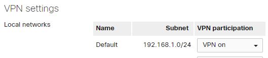
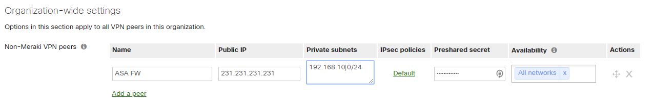
The last part would be to configure the VPN settings on the Meraki. First column you enter a name for the connection. Secondly you need to enter the IP for the ASA firewall. In the third column you decide what networks should be sent over the VPN. The same network that we defined as OBJ-ASA-Site in the ASA config. Leave the IPSec policies as Default, the connection should come up with the Default setting. At last you enter the pre shared key, press save and you should have a VPN connection.

Advertisement

Playing with the Meraki API

Lately I have started playing with the Meraki API. The API gives us the possibility to tweak and manage whatever you want to do on the Meraki devices.

To begin with you need to get the API code from the Meraki Dashboard. You can get the API code if you click on your username in the upper right corner and then proceed to My Profile. In that window you can enable and generate API keys for your scripts.

The first script you should use is the code below. This should give you a list of organizations that you have access to with the user account you generated the API key with. Normally you only have 1 organization but many might have several organizations in the list.

curl --request GET -L \
  --url https://api.meraki.com/api/v0/organizations \
  --header 'X-Cisco-Meraki-API-Key: <API key>'

This could create the follwoing output:

[{"id":"692333","name":"Organization 1"},{"id":"293843","name":"Organization 2"},{"id":"551234","name":"Organization 3"},{"id":"123476","name":"Organization 4"}]

At this point you can choose what organisation you want to create the API for. You need to take the ID and add it to the end of the URL. If I want to towrk with organization 3 I would use 551234 as the ID. After the ID you need to add networks to list the networks for the organization. I ahve added an example below:

curl --request GET -L \
  --url https://api.meraki.com/api/v0/organizations/551234/networks \
  --header 'X-Cisco-Meraki-API-Key: <API key>'

From that you should get the following output:

[{"id":"L_662029145123456789","organizationId":"551234","name":"Site 1","timeZone":"Europe/Oslo","tags":null,"type":"combined","disableMyMerakiCom":false,"disableRemoteStatusPage":true}]

You now have all the information needed to start playing around with API’s on Meraki. Meraki got alot of documentation showing what you can do. You can find the documentation here.

As an example on what you can do I can show you how to enable and disable an SSID on a network. In the Meraki documentation for SSID’s you find the various settings that you can configure. In this example I only want to change the enabled or disabled settings for the SSID. In the data-binary setting you switch between false and true to swap between disabled and enabled setting for the SSID.

curl -L -H 'X-Cisco-Meraki-API-Key: <API key>' 
  -X PUT -H 'Content-Type: application/json' 
  --data-binary '{"enabled":true}' 'https://api.meraki.com/api/v0/organizations/551234/networks/L_662029145123456789/ssids/1'

Convert Cisco Lightweight AP to Mobility Express

Hi all

Today I’m going to write a short post on how to convert a lightweight AP to an Mobility Express AP. It’s a very simple process and only takes a few minutes to complete.

First you need to download the ME image from the Cisco webpage. Extract the compressed file to a TFTP server.

Login to the AP with console access using Cisco / Cisco as username and password (this is offcourse only if you haven’t changed the password on the AP.

ap-type mobility-express tftp://<TFTP Server IP>/<filename>

When the file is uploaded the AP will reboot and load the new image. The AP will use 2 IP’s. 1 for the ME and 1 for the AP.

During my upgrade I had one issue. It failed repeatedly and I worked a while before I discovered the reason.

Image transfer complete.
Image downloaded, writing to flash...
do CHECK_ME, part1 is active part
upgrade.sh: Error: image not found.
+ do_upgrade CHECK_ME
+ [ ! -r /tmp/part.tar ]
+ loudlog Error: image not found.
+ logger -p 0 -t upgrade Error: image not found.
+ echo upgrade.sh: Error: image not found.
upgrade.sh: Error: image not found.
+ return 1
+ status=1
+ set +x
Error: Image update failed.

I read on the internet that this error could be caused due to lack of space. I had free space left so I could quickly rule that issue out. I have another ME in the same network, it seems that the ME image can’t be uploaded when there is an ME of the same L2 network as the ME you are trying to install. The issue I had dissapeared when I disconnected the other ME.

After the upgrade has been completed the ME will reboot and start a setup wizard.

Enter Administrative User Name (24 characters max): admin
Enter Administrative Password (3 to 127 characters): ********
Re-enter Administrative Password                 : ********
System Name [Cisco-dcf7.193e.4c00] (24 characters max): hostname
Enter Country Code list (enter 'help' for a list of countries) [US]: NO
Configure a NTP server now? [YES][no]: yes
Use default NTP servers [YES][no]:
Enter timezone location index (enter 'help' for a list of timezones): 14
Management Interface IP Address Configuration [STATIC][dhcp]: dhcp
Create Management DHCP Scope? [yes][NO]:
Employee Network Name (SSID)?: SSIDName
Employee Network Security? [PSK][enterprise]:PSK
Employee PSK Passphrase (8-63 characters)?: ***********
Re-enter Employee PSK Passphrase: ***********
Enable RF Parameter Optimization? [YES][no]:
Client Density [TYPICAL][Low][High]:
Traffic with Voice [NO][Yes]:

Configuration correct? If yes, system will save it and reset. [yes][NO]: yes

Configuration saved!

There is a few things that you need to get correct when going trough the options. The first one is country code. This is important to have correct freqency since it need to meet the local regulations. Since my AP’s are in Norway I choose NO as the country code.

The second one is the management interface. You can choose to have it set to static or dhcp. I normally set these ME’s up for clients and configure them with DHCP. If you choose DHCP it’s important to note the correct DHCP address when the ME boots up. As previously mentioned the AP will request 2 IP’s. 1 for the ME and 1 for the CAPWAP AP.. After the bootup you should see the following output

[*08/01/2019 17:24:33.6830] ethernet_port wired0, ip 192.168.50.108, netmask 255.255.255.0, gw 192.168.50.1, mtu 1500, bcast 192.168.50.255, dns1 195.159.0.100, dns2 8.8.8.8, domain hjortsenter.internal, vid 0, static_ip_failover false, dhcp_vlan_failover false
[*08/01/2019 17:24:33.6930] chatter: MeshNat: config_ip IP=192.168.50.108 mask=255.255.255.0 GW=192.168.50.1
[*08/01/2019 17:24:38.7614] ethernet_port wired0, ip 192.168.50.110, netmask 255.255.255.0, gw 192.168.50.1, mtu 1500, bcast 192.168.50.255, dns1 195.159.0.100, dns2 8.8.8.8, domain test.internal, vid 0, static_ip_failover false, dhcp_vlan_failover false
[*08/01/2019 17:24:38.7814] chatter: MeshNat: config_ip IP=192.168.50.110 mask=255.255.255.0 GW=192.168.50.1
[*08/01/2019 17:24:41.8004] AP IPv4 Address updated from 0.0.0.0 to 192.168.50.110

The first IP in my example is the IP for the ME (192.168.50.108)
The last IP is for the CAPWAP (192.168.50.110)

Cisco switch tries to download file from TFTP

Hi again all

When you retrieve an older Cisco switch it normally tries to download a new config file from a TFTP server. If you do not have hands on the switch it’s an easy way for setting it up. You simply add a file named switch-confg, network-confg, ciscortr.cfg or cisconet.cfg. If you do that the config will be downloaded to the switch. Below you can see the switch trying to download the file but it can’t. The reason for this is that you need to issue a command for this to stop.

no service config 

If the no service config command is issued the following entries should stop in the log.

Apr 24 2011 13:47:24.645 UTC: %SYS-4-CONFIG_RESOLVE_FAILURE: System config parse from (tftp://255.255.255.255/switch-confg) failed
Apr 24 2011 13:48:06.656 UTC: %SYS-4-CONFIG_RESOLVE_FAILURE: System config parse from (tftp://255.255.255.255/ciscortr.cfg) failed
Apr 24 2011 13:48:22.369 UTC: %SYS-4-CONFIG_RESOLVE_FAILURE: System config parse from (tftp://255.255.255.255/network-confg) failed
Apr 24 2011 13:49:04.375 UTC: %SYS-4-CONFIG_RESOLVE_FAILURE: System config parse from (tftp://255.255.255.255/cisconet.cfg) failed
Apr 24 2011 13:58:48.668 UTC: %SYS-4-CONFIG_RESOLVE_FAILURE: System config parse from (tftp://255.255.255.255/switch-confg) failed
Apr 24 2011 13:59:30.679 UTC: %SYS-4-CONFIG_RESOLVE_FAILURE: System config parse from (tftp://255.255.255.255/ciscortr.cfg) failed
Apr 24 2011 13:59:46.392 UTC: %SYS-4-CONFIG_RESOLVE_FAILURE: System config parse from (tftp://255.255.255.255/network-confg) failed
Apr 24 2011 14:00:28.403 UTC: %SYS-4-CONFIG_RESOLVE_FAILURE: System config parse from (tftp://255.255.255.255/cisconet.cfg) failed
Apr 24 2011 14:10:12.691 UTC: %SYS-4-CONFIG_RESOLVE_FAILURE: System config parse from (tftp://255.255.255.255/switch-confg) failed
Apr 24 2011 14:10:54.707 UTC: %SYS-4-CONFIG_RESOLVE_FAILURE: System config parse from (tftp://255.255.255.255/ciscortr.cfg) failed
Apr 24 2011 14:11:10.420 UTC: %SYS-4-CONFIG_RESOLVE_FAILURE: System config parse from (tftp://255.255.255.255/network-confg) failed
Apr 24 2011 14:11:52.431 UTC: %SYS-4-CONFIG_RESOLVE_FAILURE: System config parse from (tftp://255.255.255.255/cisconet.cfg) failed
Apr 24 2011 14:21:36.719 UTC: %SYS-4-CONFIG_RESOLVE_FAILURE: System config parse from (tftp://255.255.255.255/switch-confg) failed
Apr 24 2011 14:22:18.735 UTC: %SYS-4-CONFIG_RESOLVE_FAILURE: System config parse from (tftp://255.255.255.255/ciscortr.cfg) failed
Apr 24 2011 14:22:34.443 UTC: %SYS-4-CONFIG_RESOLVE_FAILURE: System config parse from (tftp://255.255.255.255/network-confg) failed
Apr 24 2011 14:23:16.564 UTC: %SYS-4-CONFIG_RESOLVE_FAILURE: System config parse from (tftp://255.255.255.255/cisconet.cfg) failed
Apr 24 2011 14:33:00.747 UTC: %SYS-4-CONFIG_RESOLVE_FAILURE: System config parse from (tftp://255.255.255.255/switch-confg) failed
Apr 24 2011 14:33:42.758 UTC: %SYS-4-CONFIG_RESOLVE_FAILURE: System config parse from (tftp://255.255.255.255/ciscortr.cfg) failed
Apr 24 2011 14:33:58.597 UTC: %SYS-4-CONFIG_RESOLVE_FAILURE: System config parse from (tftp://255.255.255.255/network-confg) failed
Apr 24 2011 14:34:40.613 UTC: %SYS-4-CONFIG_RESOLVE_FAILURE: System config parse from (tftp://255.255.255.255/cisconet.cfg) failed
Apr 24 2011 14:44:24.770 UTC: %SYS-4-CONFIG_RESOLVE_FAILURE: System config parse from (tftp://255.255.255.255/switch-confg) failed
Apr 24 2011 14:45:06.796 UTC: %SYS-4-CONFIG_RESOLVE_FAILURE: System config parse from (tftp://255.255.255.255/ciscortr.cfg) failed
Apr 24 2011 14:45:22.630 UTC: %SYS-4-CONFIG_RESOLVE_FAILURE: System config parse from (tftp://255.255.255.255/network-confg) failed
Apr 24 2011 14:46:04.636 UTC: %SYS-4-CONFIG_RESOLVE_FAILURE: System config parse from (tftp://255.255.255.255/cisconet.cfg) failed
Apr 24 2011 14:55:48.808 UTC: %SYS-4-CONFIG_RESOLVE_FAILURE: System config parse from (tftp://255.255.255.255/switch-confg) failed
Apr 24 2011 14:56:30.814 UTC: %SYS-4-CONFIG_RESOLVE_FAILURE: System config parse from (tftp://255.255.255.255/ciscortr.cfg) failed
Apr 24 2011 14:56:46.648 UTC: %SYS-4-CONFIG_RESOLVE_FAILURE: System config parse from (tftp://255.255.255.255/network-confg) failed
Apr 24 2011 14:57:28.659 UTC: %SYS-4-CONFIG_RESOLVE_FAILURE: System config parse from (tftp://255.255.255.255/cisconet.cfg) failed
Apr 24 2011 15:00:55.742 UTC: %SEC_LOGIN-5-LOGIN_SUCCESS: Login Success [user: Cisco] [Source: 10.20.10.201] [localport: 23] at 15:00:55 UTC Sun Apr 24 2011
Apr 24 2011 15:00:58.557 UTC: %SYS-5-PRIV_AUTH_PASS: Privilege level set to 15 by Cisco on vty1 (10.20.10.201)
Apr 24 2011 15:00:58.557 UTC: %PARSER-5-CFGLOG_LOGGEDCMD: User:Cisco  logged command:!exec: enable

Limit device traffic to only one MX uplink

Hi all

The Meraki MX devices gives you an easy way of automaticly use 2 uplinks. It works seamlessly but it’s hard to do some configuration that is possible on other Cisco devices.

One of those is to deny specific devices to connect over only 1 of the uplinks. Let’s say that WAN 1 is a fiber connection. You got enogh capacity to send and receive all kind of traffic. WAN 2 on the other hand is a sattelite connection. The 2 big drawbacks with sattelite is latency and speed. Sometimes even the cost per MB transferred. Often the guaranteed bandwith on a satelite connection could be as low as 64 kb/s. It’s not much bandwith for other devices then.
wanmeraki

Then the big question is, how do you limit the connection to only use WAN 1. This could be a device that sync data every hour and would generate traffic or a whole subnet with guest wifi users. You don’t want these devices use your costly satelite connection. You do most likely need it for business critical applications.

I spent a few good hours trying to find a solution to this. I asked help from Meraki and various forums. I always got told that traffic shaping should help etc. But the only thing it does is giving me the preferred uplink, it never blocks the traffic from going online if the other WAN connection is down.

The solution I came up with was to turn off NAT when you use the interface that should be blocked. All the devices behind the Meraki that should be blocked does need to be in a seperate VLAN. In version 15 you can exclude specific VLAN from the NAT policy on the uplinks. The traffic will then stop since there is no return route for the traffic (as long as youo don’t add a static route).

So in the above example we want VLAN 20 to only have access over WAN 1 and not WAN 2. You start by finding the network you want to do the change on in the Meraki Dashboard. Then go to Security & SD-WAN and Adressing and VLAN’s on the left side. In the bottom of the page you have NAT exceptions where you can choose to disable NAT on the different uplinks. In my screenshot I have excepted Crew network from the NAT policy. With this config the devices on Crew VLAN can’t use WAN 2/Uplink 2.
NAT meraki

Backup and restore config of Mobility Express.

Hi all

Lately I have been working with the mobility express AP’s from Cisco.  One of the important things to do when you set up new equipment is to have a backup and restore policy for the config.. I chose the easy way out using tftp, it’s the quickest and easiest way to transfer files as long as you have the tftp server secured. The other option you have is ftp.

transfer upload mode tftp
Sets the mode to tftp, you can also choose ftp but then you need to add in username and password too.

transfer upload datatype config
Choose config as the information to store on the server

transfer encrypt enable
Turns on encryption for the file

transfer encrypt set-key supersecret
Gives the encryption a password

transfer upload serverip 10.10.10.10
Gives the ME an IP to the server where to store the config

transfer upload filename MEconfig.cfg
Filename for the config.

transfer upload start
Start the upload.

transfer upload mode tftp
transfer upload datatype config
transfer encrypt enable
transfer encrypt set-key supersecret
transfer upload serverip 10.10.10.10
transfer upload filename MEconfig.cfg
transfer upload start

You should then get the following output.

Mode……………………………………… TFTP
TFTP Server IP…………………………….. 10.10.10.10
TFTP Path………………………………….
TFTP Filename……………………………… MEconfig.cfg
Data Type…………………………………. Config File
Encryption………………………………… Enabled

Are you sure you want to start? (y/N) y

File transfer operation completed successfully.

So far you have done the backup. Then the second most important thing comes, do the restore. It’s almost the same, but you swap out upload with download.

transfer download datatype config
transfer download mode tftp
transfer encrypt enable
transfer encrypt set-key supersecret
transfer download serverip 10.10.10.10
transfer download filename MEconfig.cfg
transfer download start

After the commands have been entered you should see the following output.

Mode............................................. TFTP
Data Type........................................ Config
TFTP Server IP................................... 10.10.10.10
TFTP Packet Timeout.............................. 6
TFTP Max Retries................................. 10
TFTP Path........................................
TFTP Filename.................................... MEconfig.cfg
Encrypt/Decrypt Flag............................. Enabled

Warning: Downloading configuration will cause the controller to reset...

This may take some time.
Are you sure you want to start? (y/N) y

TFTP Config transfer starting.

TFTP receive complete... updating configuration.

CCO Username & Password will NOT be imported. Please Re-Configure the Credentials 'transfer download ap-images cco-username '
'transfer download ap-images cco-password ' after bootup for Image Download

TFTP receive complete... storing in flash.

Sync config to peers.

System being reset.


Using python and telnet

So here we go with my first test of python. After reading a few blogs on python  and watched some videos I created my first script that actually does something on a switch. It’s not actually super useful but it’s something!

I got a Ubuntu machine that I connect to using SSH. On this computer I have used nano since it’s the only default editing tool I know how to use on a linux device (I really hate vi for text editing). When I get a little bit further along I’m going to set up my notepad++ client to automaticly upload my scripts since I like a little bit better to do text configs on my windows.

I’ll try to go trough the script almost line by line. I found the example in the python website and a youtube video.

import getpass 
import sys 
import telnetlib

The first part is importing moules to make the programming easier. In short terms it saves me alot of time making my own way of using the telnet protocol.

host = "10.10.10.30" 
user = raw_input("Username: ") 
password = getpass.getpass()

The second part is handeling the connection to the device. The first line is creating a variable called host. This is the IP or dns name for the device you are connecting to.
Second line is creating the variable called user. The information does it get using an input when you run the command. You can see when to input the information when Username: is displayed.
The last line in this section is creating the variable password. This uses the imported module password to not display the text when entered and hides it for us.

tn = telnetlib.Telnet(host)

This part is telling the python script to connect to the device with the IP address in the previous section. You can see the variable is with red  text.

tn.read_until("Username: ") tn.write(user + "\n") 
if password: 
    tn.read_until("Password: ") 
    tn.write(password + "\n")

Now to the login part of the script. It first skips the MOTD or whatever is shown before the login prompt. The script is continiuing until it sees Username:
When it reachs Username: it will enter the user variable (marked by red)  that you enter in the previous section. This is ended by a \n to signal that the script should press enter. The script will then read until Password: shows up and ad the variable password ended with a \n. Pretty much the same as user

tn.write("enable\n") 
tn.write("Cisco\n") 
tn.write("conf t\n") 
tn.write("vlan 20\n") 
tn.write("name guest\n") 
tn.write("vlan 100\n") 
tn.write("name production\n") 
tn.write("end\n") 
tn.write("exit\n")

This part should be familiear to most cisco engineers. You can see the different commands in each line ended by \n to simulate the press of the enter key. It basicly sends out what you type in the command window.

print tn.read_all()

In the end it reads everything out that has been sent using the telnet session.

The complete script will then be this:

import getpass 
import sys 
import telnetlib 
host = "10.10.10.30" 
user = raw_input("Username: ") 
password = getpass.getpass() 
tn = telnetlib.Telnet(host) 
tn.read_until("Username: ") 
tn.write(user + "\n") 
if password: 
  tn.read_until("Password: ") 
  tn.write(password + "\n") 
tn.write("enable\n") 
tn.write("Cisco\n") 
tn.write("conf t\n") 
tn.write("vlan 20\n") 
tn.write("name guest\n") 
tn.write("vlan 100\n") 
tn.write("name production\n") 
tn.write("end\n") 
tn.write("exit\n") print tn.read_all()

I have also attached a screenshot from the Linux server when I’m running the script

telnetcreatevlan

Cisco and python programming

I have decided I want to try to program cisco switches and devices using python. At the moment my programming skills are limited to simple if and else. I now have a plan to configure a linux server with python on to do all my scripting.

The plan is to try to upload the different scripts I create here as I go along. Hopefully it will get useful for others too in the end and not just something for me. I will try to use various youtube videos and pages to learn me the diffferent things with oython and will link them from my upcoming posts as I go along.

If you have something you want me to write about or create a script it’s greatly apreciated!

Rebooting a switch in a stack

During some recent switch replacement work I did I noticed not all my stacks had the correct IOS version, or wai. The correct thing to say would be that one of the switches did not have the correct IOS version. The resone for this was that I upgraded to the correct IOS before I created the stack and then connected the second switch to the stack. When the second switch got connected the stack was left with 2 IOS versions.

To solve this issue I used the archive download-sw command to download only the new OS to the switch. To do this I first run show version to know the stack number of the switch.
iosshversion

From the show version I could get the stack number of the switch that needs the IOS upgrade. Be aware that the screenshot is showing the IOS version the same on all switches, so there is no difference in the screenshot. In my blog post I wanted to upgrade switch 2.

archive download-sw /destination-system 2 tftp://1.1.1.1/IOS.tar

To complete the upgrade and not to reboot the whole switch you enter the command

reboot slot 2

This will only reboot the switch that has the stack number specified.

Changing IP of HA WLC controller.

Today I did change IP of one of our HA Wireless Controllers. Since the company I work for got bought last year we have to change IP of our systems to fit into our new and bigger network.

Changing the IP address isn’t a big thing and you can do it without any downtime on the AP’s if you run flexconnect. If you run in local mode you will be looking at a short downtime. If you want to do it with the minimal of downtime you need a third controller that can host your AP’s while the HA cluster is down.

If you have a third controller that can host your AP’s you have to make sure that the mobility groups are configured and working to your HA. You can check this in the following menu: Controller -> Mobility Management -> Mobility Groups. In this menu all your mobility groups are listed. If the mobility group towards the controller is Up you should see it on the right side of the page. You also have to check this on the HA controller.
MobilityGroupCheck

If the mobility group is up and running then the next thing is to change primary controller for the AP’s. This is a very easy task but it’s time consuming if you don’t have Cisco Prime ( I got that luckily). From Cisco Prime you can just send out a template to all the AP’s and make them move to another primary controller. If you want to do it manually you can do it to. Then you have to first open an AP and choose High Availability. Then you configure the third controller as Primary. Within the next few minutes all the AP’s should be moved to a new controller.
HASettingAP

When there is no connected AP’s left we can start the work to re-IP the HA controller. The first thing we have to do is to break the HA cluster. We are not able to change the IP without breaking the cluster. When breaking the cluster there will also be a restart, so if you don’t have another controller for your AP’s, be ready for some downtime!

To disable the cluster you go to  Controller -> Redundancy -> Global Configuration. In the lower part of the page you have the option to Disable or Enable the cluster. Set the drop down to Disabled and press Apply in the top right corner. The controller will then ask you if you are sure about breaking the cluster and that the controller will restart. Accept this and wait for a few minutes.
DisableCluster

The WLC will after a few minutes boot up again on the same IP address as before. Then you should go to the Interface menu to change the management IP address.
InterfaceOverview1.jpg

Change the IP Address, Netmask and Gateway to the new values and press Apply. You will now loose connection and need to connect on the new IP’s It’s very important to enter the correct IP’s so you don’t loose contact (or you could use the integrated service port if you have a 550x).
ManagementInterface

The next interface you need to change is the redundancy management IP address. This IP should be in the same subnet as the management IP. So unless you change the IP to something in the same subnet as your previous IP you need to change this IP also. This IP also needs to match the Redundancy mgmt IP in Controller -> Redundancy -> Global Configuration.
2016-08-17_09-23-42.jpg

The last thing you need to do o this controller is go back to Controller -> Redundancy -> Global Configuration and change the IP’s for the Redundancy mgmt IPs and enable the cluster again.
2016-09-06_22-53-56

You should now be finished With the first Controller. The IP for the WLC HA is now active and if you want to move the AP’s to the New Controller you can do that now. You shoudl be able to Connect to the remaining Controller on the old management IP address. You should repeat the steps for changing the Redundancy mgmt IP and Redundancy port IP. When this is done you only need to enable the cluster on this Controller also and the HA should be working again as before.

When you have enable HA on the second Controller you can go to Monitor -> Redundancy -> Summary. There you will be able to see if the HA cluster is running successfully again.
2016-09-06_23-28-44

Your cluster should now be working correctly. If you got questions or feedback please leave a comment!